This is the second part of a series on Hydraulics and Filtration, which aims to serve as a general guide on the subject. This part analyzes common damages in hydraulic systems caused by contamination.
Heat, assembly processes and contaminants together cause a very large portion of problems in hydraulic systems and their components. Problems caused by heat are usually related to design and manufacturing processes along with the materials used, while problems caused during assembly generally concern sealing and fittings. It is contamination that causes our greatest concerns for hydraulic systems. According to designers and users of these systems, only a quarter of the problems in hydraulic components are not caused directly by contaminants.
Entry of contaminants into a system can inflict heavy costs on the owners by causing serious disruptions to the core functions of hydraulic fluids. These functions are as follows:
- Acting as a force transmission medium
- Lubrication of inner moving parts
- Acting as a heat transfer medium
- Filling the gaps between moving components
If any of these functions are disrupted, the hydraulic system will not operate as intended. However, proper use and maintenance of fluids can help prevent unexpected downtime and thus save thousands of euros for production plants. Problems caused by contaminants can inflict a wide range of costs on a system:
- Costs of downtime
- Costs of component replacement
- Costs of fluid change
- Costs of fluid elimination
- Increased maintenance costs
- Increased amount of waste
Contaminant-caused damage usually occurs in the following forms:
- Clogging
- Component wear
- Formation of rust or other types of oxidation
- Formation of chemical compounds
- Altered properties of additives
- Bacterial growth
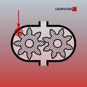
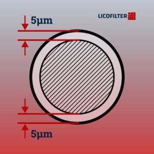
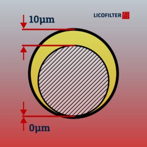
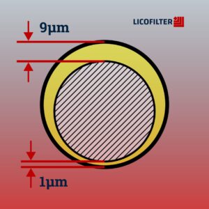
Hydraulic fluid maintains the space between moving components by forming a lubricating film. Ideally, this film is thick enough to fill component clearances. This keeps wear at low levels and increases component lifespan, which could reach up to several million cycles.
In Hydraulics, “clearance” is defined as the space between components, either moving or fixed. Clearances for different types of hydraulic components are determined based on component role and expected efficiency.
Clearances for common hydraulic components are listed below:
Common clearances in hydraulics
| Component | Clearance (microns) |
| Plain Bearing | 0.5 |
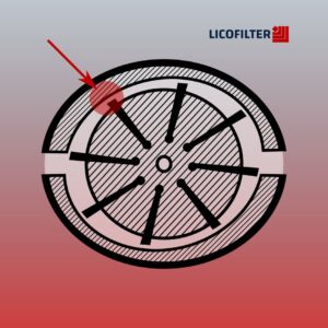
| Vane Pump (vane tip to outer ring) | 0.5-1 |
| Gear Pump (gear to side plate) | 0.5-5 |
| Servo Valve (spool to sleeve) | 1-4 |
| Hydrostatic Bearing | 1-25 |
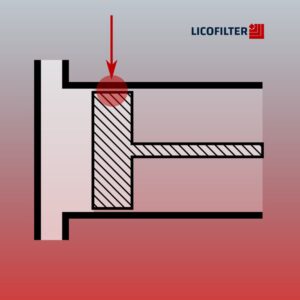
| Piston Pump (piston to bore) | 5-40 |
| Servo Valve Flapper Wall | 18-63 |
| Hydraulic Actuator | 50-250 |
| Servo valve orifice | 130-450 |
Lubrication is achieved by introducing a film of lubricating fluid in the clearance. The thickness of this film depends on the designed clearance, the load under which the component operates, component velocity and lubricant viscosity.
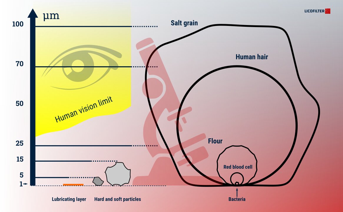
Comparing the component clearances with some common particle sizes given below can give a clear picture of how sensitive each hydraulic component is to various solid particles. The illustration can help with picturing the relative sizes of these particles.
Relative particle sizes
| Particle or Range | Size (microns) | Size (inches) |
| Grain of Common Salt | 100 | 0.0039 |
| Human Hair | 70 | 0.0027 |
| Lower Limit of Human Vision | 40 | 0.0016 |
| Flour | 25 | 0.001 |
| Red Blood Cells | 8 | 0.0003 |
| Bacteria | 2 | 0.0001 |